
AWS1 - Arduino Workshop IntroMy Arduino board is connected to a Banana Pi with VS Code serverPrototyping with TinkerCADCreate & ShareConstraints and chancesLearningsAWS1 Assignment / Deliverables AWS1 - 3C - BlinkMultipleAWS1 - 4C - FadeLEDAnalogAWS1 - 6C - FadeLEDPotAWS1 - 7C - LEDMatrixPotAWS2 - Arduino advanced - LED Matrixes and more AWS2 - 9B - PiezoMelodyAWS2 - 9D - PiezoInstrumentAWS2 - 10D - TempSense / HumidSense + Matrix AWS2 - 11D - SocialDistanceAWS3 - Making sense of Data + Servo magicAWS3 Deliverables AWS3 - 12E - ProcessingOutputAWS3 - 13E - TwoButtonsAWS3 - 14C - ServoKnobAWS3 - 15C - CapaTouchAWS3 Bonus (Or tinkering? Whatever) Further thoughtsThe Emotional MatrixFrom Input to outputSwitching devicesInput to output, next level
AWS1 - Arduino Workshop Intro
Today we kicked our HCI day off with some Arduino basics. While I was trying to get my setup running again and Visual Studio Code kept me busy with SSH connecting loops, , during the course we learned more about basics such as the crucialty of resistors, proper circuits.

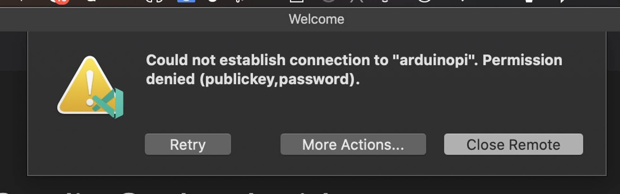
Wait, which SSH loops - Why Visual Studio Code for Arduino?
My Arduino board is connected to a Banana Pi with VS Code server
Owning one of the newer MacBooks that were designed for bad typing experience, noisy fans and the minimal possible port(un)availability I am facing unusual challenges. Also due to the fact I fried one of my ports once before I became rather cautious about this device and using offbrand-adapters.
Having that challenge combined with the assumption, we would work on that project in a group setting and would need to collaborate, I followed a different approach from the beginning
Prototyping with TinkerCAD
- So far, I had minor issues where the circuit did not work although copied 1:1 from another setup. What I was trying to do is to copy a setup, adjust the code and have 2 similar setups next to each other. I was messing around for 20 minutes until I realized it can only be fixed by building it again from scratch. Some information might get lost in the clipboard (JSON, whatever)
Create & Share


Constraints and
Constraints and chances
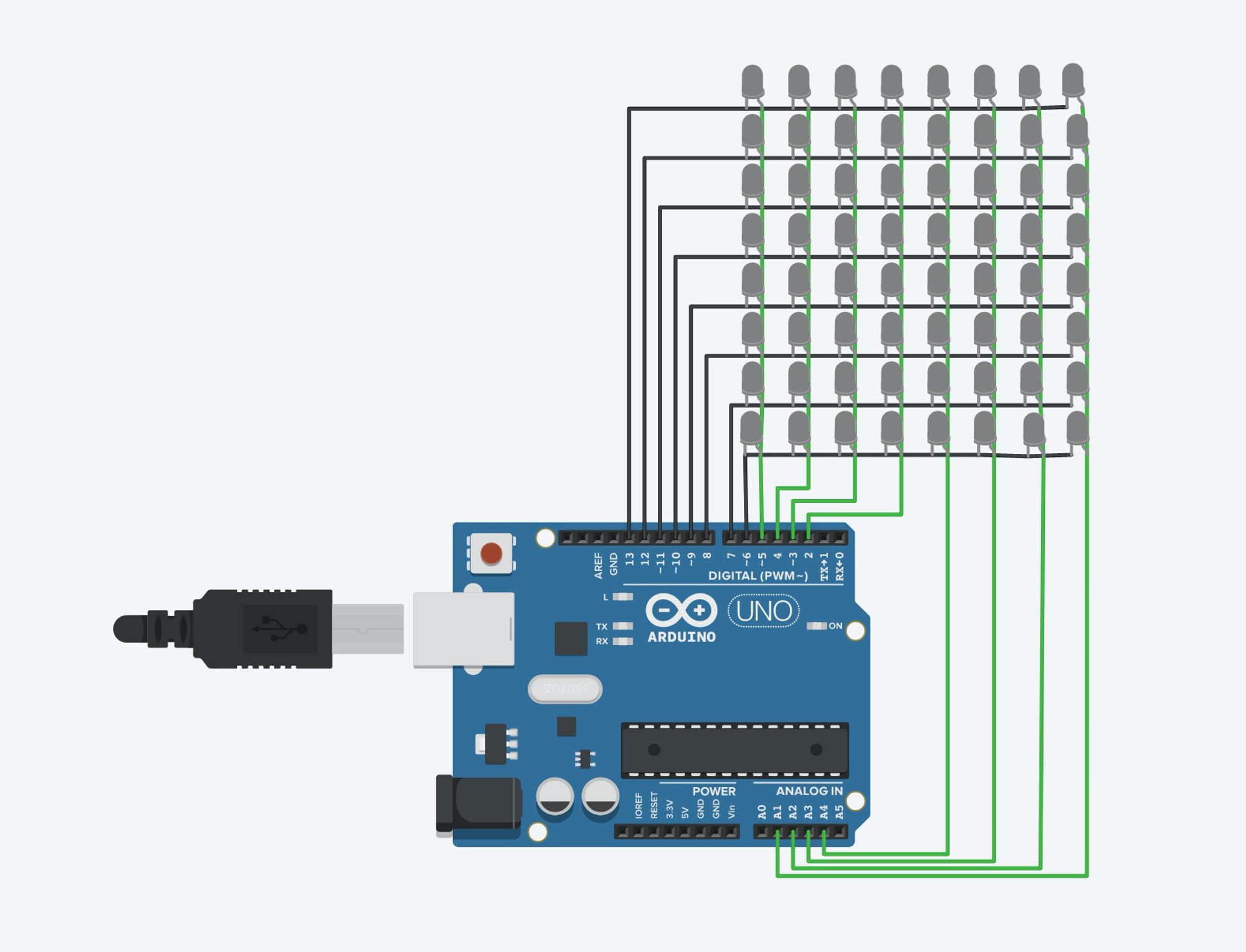
In the last assignment I found that TinkerCAD had no preset for the LED matrix module with socket (4 cables). However a TinkerCAD community member uploaded an alternative approach for that

Learnings
- Only pins with strikes are capable of doing Pulse With Modulation (PWM) and thus can be used to dim LEDs
- PIN13 is linked to the internal LED - So adressing the internal LED also triggers PIN 13
AWS1 Assignment / Deliverables
Arduino workshop 1: 3C, 4C, 6C, 7C
AWS1 - 3C - BlinkMultiple
I was aiming to make the code more scalable, but it turned out I was lacking a basic certain logic as the LEDs were not working at the same time
Partially working solution (Code)
/*
  Blink

  Turns an LED on for one second, then off for one second, repeatedly.

  Most Arduinos have an on-board LED you can control. On the UNO, MEGA and ZERO
  it is attached to digital pin 13, on MKR1000 on pin 6. LED_BUILTIN is set to
  the correct LED pin independent of which board is used.
  If you want to know what pin the on-board LED is connected to on your Arduino
  model, check the Technical Specs of your board at:
  https://www.arduino.cc/en/Main/Products

  modified 8 May 2014
  by Scott Fitzgerald
  modified 2 Sep 2016
  by Arturo Guadalupi
  modified 8 Sep 2016
  by Colby Newman

  This example code is in the public domain.

  http://www.arduino.cc/en/Tutorial/Blink
*/

// the setup function runs once when you press reset or power the board
void setup() {
  // initialize digital pin LED_BUILTIN as an output.
    pinMode(13, OUTPUT); //Green LED
    pinMode(12, OUTPUT); //Yellow LED

}

// the loop function runs over and over again forever
void loop() {
    blinkLED(12,1000);
}

void blinkLED(int pinNum, int blinkDuration) {
    digitalWrite(pinNum, HIGH);
    offLED(pinNum, blinkDuration);
    pinNum=pinNum+1;
    blinkDuration=blinkDuration/2;
    offLED(pinNum, blinkDuration/2);

}
void offLED(int pinNum,int blinkDuration){

    delay(blinkDuration);                       // wait for a second
    digitalWrite(pinNum, LOW);


}
Working solution (Code)
/*
  Blink

  Turns an LED on for one second, then off for one second, repeatedly.

  Most Arduinos have an on-board LED you can control. On the UNO, MEGA and ZERO
  it is attached to digital pin 13, on MKR1000 on pin 6. LED_BUILTIN is set to
  the correct LED pin independent of which board is used.
  If you want to know what pin the on-board LED is connected to on your Arduino
  model, check the Technical Specs of your board at:
  https://www.arduino.cc/en/Main/Products

  modified 8 May 2014
  by Scott Fitzgerald
  modified 2 Sep 2016
  by Arturo Guadalupi
  modified 8 Sep 2016
  by Colby Newman

  This example code is in the public domain.

  http://www.arduino.cc/en/Tutorial/Blink
*/

// the setup function runs once when you press reset or power the board
void setup() {
  // initialize digital pin LED_BUILTIN as an output.
    pinMode(13, OUTPUT); //Green LED
    pinMode(12, OUTPUT); //Yellow LED

}

// the loop function runs over and over again forever
void loop() {
    blinkLED();
}


void blinkLED() {
    digitalWrite(13, HIGH);
    digitalWrite(12, HIGH);
    delay(500);
    digitalWrite(13, LOW);
    delay(500);
    digitalWrite(13, HIGH);
    digitalWrite(12, LOW);
    delay(500);
    digitalWrite(13, LOW);
    delay(500);
}
AWS1 - 4C - FadeLEDAnalog
The solution was pretty straight forward and did not require a second for loop as expected. Negating the value for the second LED was sufficient.
Working solution (Code)
int greenLedPin = 10; int yellowLedPin = 9;
void setup() {
     pinMode(greenLedPin, OUTPUT);
     pinMode(yellowLedPin, OUTPUT);
}
void loop() {
    for (int brightness=0; brightness <256; brightness++){
         analogWrite(greenLedPin, brightness);
         analogWrite(yellowLedPin, brightness*-1); //negate value of brightness for reverse fade
         delay(10);
    }
}
AWS1 - 6C - FadeLEDPot
Working solution (Code)
float sensorValue = 0; // variable for sensor value
int sensorPin = A0; // variable for sensor pin
int greenLedPin = 10; int yellowLedPin = 9;

void setup() {
    sensorValue = (sensorValue/1023)*255;
    pinMode(sensorPin, INPUT);
    Serial.begin(9600);
    pinMode(greenLedPin, OUTPUT);
    pinMode(yellowLedPin, OUTPUT);

}

void loop() {
    sensorValue = analogRead(sensorPin); // read the value/voltage on the sensor pin and // store that value in the variable sensorValue
    sensorValue = (sensorValue/1023)*255;
    analogWrite(greenLedPin, sensorValue);
    analogWrite(yellowLedPin, sensorValue*-1);
    Serial.println(sensorValue); // print out sensorValue to the Serial Monitor
    delay(200); // delay for 0.2 seconds
}
AWS1 - 7C - LEDMatrixPot
This assignment I wanted to use to use other approaches for saving LED definitions. I chose to follow the process of using uint64_t hashes defined in an array in the beginning of the code instead of byte code. (As described here https://xantorohara.github.io/led-matrix-editor/#3c7ec3c300666600|c3e77e3c00666600)
Working solution (Code)
#include "LedControl.h"
/*
DIN connects to pin 12 CLK connects to pin 11 CS connects to pin 10
*/
LedControl lc = LedControl(11,10,9,1);

/*
const byte IMAGES[][8] = {
{
  B00000000,
  B01100110,
  B01100110,
  B00000000,
  B11000011,
  B11000011,
  B01111110,
  B00111100
},{
  B00000000,
  B01100110,
  B01100110,
  B00000000,
  B00111100,
  B01111110,
  B11100111,
  B11000011
},{
  B00000000,
  B01100110,
  B01100110,
  B00000000,
  B00000000,
  B11111111,
  B11111111,
  B00000000
}};

const int IMAGES_LEN = sizeof(IMAGES)/8;
*/

// As described in https://xantorohara.github.io/led-matrix-editor/#3c7ec3c300666600|c3e77e3c00666600|0000000000666600
const uint64_t IMAGES[] = {
  0x3c7ec3c300666600,
  0xc3e77e3c00666600,
  0x00ffff0000666600
};
const int IMAGES_LEN = sizeof(IMAGES)/8;

void setup() {
    lc.shutdown(0,false); // Turn matrix on, no power saving
    lc.setIntensity(0,8); // Set brightness to a medium value
    lc.clearDisplay(0); // Clear the display
    Serial.begin(9600);
}


void displayImage(uint64_t image) {
  for (int i = 0; i < 8; i++) {
    byte row = (image >> i * 8) & 0xFF;
    for (int j = 0; j < 8; j++) {
      lc.setLed(0, i, j, bitRead(row, j));
    }
  }
}
int i = 0;

void loop(){
    int sensorValue = analogRead(A0); // read sensor, 0-1023
    Serial.println(sensorValue);
    sensorValue = map(sensorValue, 0, 1000, 0, 7);
    // remap the value 0-7. (1000 eliminates noise)
    /* Map an analog value to 8 bits (0 to 255)
    Parameters

    value: the number to map.
    fromLow: the lower bound of the value’s current range.
    fromHigh: the upper bound of the value’s current range.
    toLow: the lower bound of the value’s target range.
    toHigh: the upper bound of the value’s target range.


     */

    if (sensorValue>6){
        displayImage(IMAGES[0]);

    }else if (sensorValue>3){
        displayImage(IMAGES[2]);

    }else{
        displayImage(IMAGES[1]);
    }
    lc.clearDisplay(0); // Clear the display

}
AWS2 - Arduino advanced - LED Matrixes and more
AWS2 - 9B - PiezoMelody
I already did the same with my ESP8266 but made it again to have the portfolio complete.
Working solution (Code)
int speakerPin = 8;
void setup() {
    pinMode(speakerPin, OUTPUT);
}
void loop() {
    tone(speakerPin, 262, 200);
    tone(speakerPin, 294, 200); delay(250);
    tone(speakerPin, 330, 200); delay(250);
    tone(speakerPin, 262, 200); delay(500);
delay(250);
}
AWS2 - 9D - PiezoInstrument
Great application case to use the map function again - one line but very powerful. (For demonstration purposes I lowered the range for the video to 600, as this reflected the current light in my room)
An additional idea would be to find the current light value in the setup section and set it as range, so pressing the reset button would allow to setup and use the instrument in a different light setting.
Working solution (Code)
int sensorValue = 0; // variable for sensor value
int sensorPin = A0; // variable for sensor pin
int speakerPin = 8; // variable for sensor pin

void setup() {
    pinMode(sensorPin, INPUT);
    Serial.begin(9600);
}

void loop() {
    int sensorValue = analogRead(A0);
    sensorValue = map(sensorValue, 0, 1000, 100, 2000);
    //mapping to freq range

    Serial.println(sensorValue);
    tone(speakerPin, sensorValue, 200);
    delay(250);
    noTone(speakerPin);
    delay(100);
}
AWS2 - 10D - TempSense / HumidSense + Matrix
I can't figure out know where my temparature sensor went - but I added the code as it should work using the suggested analog sensor. What I had flying around however was a DHT11 sensor which features humidity detection as well. With the whole corona aerosol awareness going onI was very curious on making my "invisible" droplets visible just by breathing towards the sensor.
The results are shocking.


Working solution (Code)
#include <dht.h>
#include <MD_MAX72xx.h>

dht DHT;

#define DHT11_PIN 7
//int sensePin = A0;  //This is the Arduino Pin that will read the sensor output
//int sensorInput;    //The variable we will use to store the sensor input
//double temp;        //The variable we will use to store temperature in degrees.


// Define the number of devices we have in the chain and the hardware interface
// NOTE: These pin numbers will probably not work with your hardware and may
// need to be adapted
#define HARDWARE_TYPE MD_MAX72XX::PAROLA_HW
#define MAX_DEVICES	4

#define CLK_PIN   11  // or SCK
#define DATA_PIN  10  // or MOSI
#define CS_PIN    9  // or SS

MD_MAX72XX mx = MD_MAX72XX(HARDWARE_TYPE, DATA_PIN, CLK_PIN, CS_PIN, MAX_DEVICES);
#define  DELAYTIME  100  // delay between animations in milliseconds


void setup(){
  Serial.begin(9600);
  mx.begin();

}

void loop()
{
 /* sensorInput = analogRead(A0); //read the analog sensor and store it
  temp = (double)sensorInput / 1024;   //find percentage of input reading
  temp = temp * 5;                     //multiply by 5V to get voltage
  temp = temp - 0.5;                   //Subtract the offset
  temp = temp * 100;                   //Convert to degrees
  Serial.print("Current Temperature: ");
  Serial.println(temp); */

  int chk = DHT.read11(DHT11_PIN);
  Serial.print("DHT11 Temperature = ");
  Serial.println(DHT.temperature);
  Serial.print("DHT11 Humidity = ");
  Serial.println(DHT.humidity);
  float humidityValue = DHT.humidity;
  displayRow(humidityValue);
  delay(2000);


}

void displayRow(float humidityValue){
  humidityValue = map(humidityValue, 50, 100, 0, 7);
  Serial.print("Displayed humidity ");
  Serial.println(humidityValue);
  mx.clear();
  for(humidityValue<7;humidityValue--;){
    mx.setRow(humidityValue,0xff);
  }

}
AWS2 - 11D - SocialDistance
As the LED Matrix was still connected, I decided to use it for the distance sensor (Would consider it more visible and clear as well )
Working solution (Code)
#include <MD_MAX72xx.h>
const int echoPin = 6;
const int trigPin = 7;
//int ledPin = 8;

#define HARDWARE_TYPE MD_MAX72XX::PAROLA_HW
#define MAX_DEVICES	4

#define CLK_PIN   11  // or SCK
#define DATA_PIN  10  // or MOSI
#define CS_PIN    9  // or SS

MD_MAX72XX mx = MD_MAX72XX(HARDWARE_TYPE, DATA_PIN, CLK_PIN, CS_PIN, MAX_DEVICES);
#define  DELAYTIME  100  // delay between animations in milliseconds

void setup() {
     pinMode(echoPin, INPUT);
     pinMode(trigPin, OUTPUT);
     Serial.begin(9600);
     //pinMode(ledPin, OUTPUT);
    mx.begin();

}

void loop() {
    // send a pulse
    digitalWrite(trigPin,LOW);
    delayMicroseconds(2);
    digitalWrite(trigPin,HIGH);
    delayMicroseconds(5);
    digitalWrite(trigPin,LOW);
    // wait for the echo
    long duration = pulseIn(echoPin, HIGH);
    // convert the time into a distance, the speed of sound is 29 microseconds per centimeter,
    //the pulse traveled forth and back, so we divided the distance by 2
    int cm = duration / 29 / 2;
    Serial.print(cm);
    Serial.println();
    displayRow(cm);

    delay(100);
}

void displayRow(int distanceValue){
  distanceValue = map(distanceValue, 2, 150, 7, 0);
  Serial.print("Displayed VALUE ");
  Serial.println(distanceValue);
  mx.clear();
  if(distanceValue>6){

    mx.setRow(0,B10011001);
    mx.setRow(1,B10011001);
    mx.setRow(2,B10011001);
    mx.setRow(3,B10011001);
    mx.setRow(4,B10011001);
    mx.setRow(5,B10011001);
    mx.setRow(6,B00000000);
    mx.setRow(7,B10011001);

        delay(1000);

    }
  for(distanceValue<7;distanceValue--;){
    mx.setRow(distanceValue,0xff);
  }


}
AWS3 - Making sense of Data + Servo magic
In the third workshop we made the first move towards getting data out of the Arduino environment.
Just as the console in JavaScript, the Arduino has a serial output monitor.
In the assignment we connected this serial output to Processing, which we got to be using in the programming bootcamp back in 2018.
As I am running a slightly different setup at home (See: Remote development with Arduino + your favourite micro computer (e.g. Raspberry Pi)) ., with the Arduino not being physically connected to my Laptop I was thinking about a different approach on making the data available.


This however tuned out to be beyond the scope of this workshop so I hooked up the Arduino to my laptop.
AWS3 Deliverables
Arduino workshop 3: 12E, 13E, 14C, 15C
AWS3 - 12E - ProcessingOutput
After hurdles in the beginning (I was trying to gather data from the Arduino connected to my Raspberry Pi), I decided to connect it straight to my computer. I used the distance sensor and slightly modified the Processing file so it shows a blue sign with "AFSTAND HOUDEN", but only when you get close. Funny, right?
Working solution (Code) - Arduino
const int echoPin = 6;
const int trigPin = 7;
float sensorValue;

void setup() {
     pinMode(echoPin, INPUT);
     pinMode(trigPin, OUTPUT);
     Serial.begin(9600);
     //pinMode(ledPin, OUTPUT);

}

void loop() {
    // send a pulse
    digitalWrite(trigPin,LOW);
    delayMicroseconds(2);
    digitalWrite(trigPin,HIGH);
    delayMicroseconds(5);
    digitalWrite(trigPin,LOW);
    // wait for the echo
    long duration = pulseIn(echoPin, HIGH);
    // convert the time into a distance, the speed of sound is 29 microseconds per centimeter,
    //the pulse traveled forth and back, so we divided the distance by 2
    int cm = duration / 29 / 2;
    Serial.println(cm);
    delay(100);
}
Working solution (Code) - Processing
import processing.serial.*;
Serial myPort;
String sensorReading="";

void setup() {
  size(400, 400);
  myPort = new Serial(this, Serial.list()[4], 9600);
  // instead of 5, choose what everserial port the Arduino connects to
  myPort.bufferUntil('\n'); }

  void draw() {
  int sensorReadingNum = Integer.parseInt(sensorReading.trim());
  int sensorReadingNeg =   (sensorReadingNum*-1)+200;

  background(255);

  fill(0,128,255);
  textSize(12);

  text("Sensor Reading: " + sensorReading, 20, 20);

  rectMode(CENTER);
  rect(width/2, height/2, float(sensorReadingNeg*2), float(sensorReadingNeg), 9);
  textSize(32);
  fill(255, 255, 255);
  textAlign(CENTER);{

  if(sensorReadingNum<20) {
  text("AFSTAND HOUDEN!", width/2, height/2);}

    }
  }
  void serialEvent (Serial myPort) { sensorReading = myPort.readStringUntil('\n');
}
AWS3 - 13E - TwoButtons
The solution was pretty straight forward and did not require a second for loop as expected. Negating the value for the second LED was sufficient.
Working solution (Code)
/*
  Button

  Turns on and off a light emitting diode(LED) connected to digital pin 13,
  when pressing a pushbutton attached to pin 2.

  The circuit:
  - LED attached from pin 13 to ground
  - pushbutton attached to pin 2 from +5V
  - 10K resistor attached to pin 2 from ground

  - Note: on most Arduinos there is already an LED on the board
    attached to pin 13.

  created 2005
  by DojoDave <http://www.0j0.org>
  modified 30 Aug 2011
  by Tom Igoe

  This example code is in the public domain.

  http://www.arduino.cc/en/Tutorial/Button
*/

// constants won't change. They're used here to set pin numbers:
const int buttonPinL = 2;     // the number of the pushbutton pin
const int buttonPinR = 3;     // the number of the pushbutton pin
const int ledPin =  13;      // the number of the LED pin

// variables will change:
int buttonStateL = 0;         // variable for reading the pushbutton status

int buttonStateR = 0;         // variable for reading the pushbutton status

void setup() {
  // initialize the LED pin as an output:
  pinMode(ledPin, OUTPUT);
  // initialize the pushbutton pin as an input:
  pinMode(buttonPinL, INPUT);
  pinMode(buttonPinR, INPUT);

}

void loop() {
  // read the state of the pushbutton value:
  buttonStateL = digitalRead(buttonPinL);
  buttonStateR = digitalRead(buttonPinR);

  // check if the pushbutton is pressed. If it is, the buttonState is HIGH:
  if (buttonStateL == HIGH || buttonStateR == HIGH) {
    // turn LED on:
    digitalWrite(ledPin, HIGH);
  } else {
    // turn LED off:
    digitalWrite(ledPin, LOW);
  }
}
AWS3 - 14C - ServoKnob
The solution was pretty straight forward and did not require a second for loop as expected. Negating the value for the second LED was sufficient.
Working solution (Code)
/*
 Controlling a servo position using a potentiometer (variable resistor)
 by Michal Rinott <http://people.interaction-ivrea.it/m.rinott>

 modified on 8 Nov 2013
 by Scott Fitzgerald
 http://www.arduino.cc/en/Tutorial/Knob
*/

#include <Servo.h>

Servo myservo;  // create servo object to control a servo

int potpin = 0;  // analog pin used to connect the potentiometer
int val;    // variable to read the value from the analog pin

void setup() {
  myservo.attach(9);  // attaches the servo on pin 9 to the servo object
}

void loop() {
  val = analogRead(potpin);            // reads the value of the potentiometer (value between 0 and 1023)
  val = map(val, 0, 1023, 0, 160);     // scale it to use it with the servo (value between 0 and 180)
  myservo.write(val);                  // sets the servo position according to the scaled value
  delay(15);                           // waits for the servo to get there
}
AWS3 - 15C - CapaTouch
I was really excited about this assignment as it could play an interesting role in a project I was thinking about for a while now.
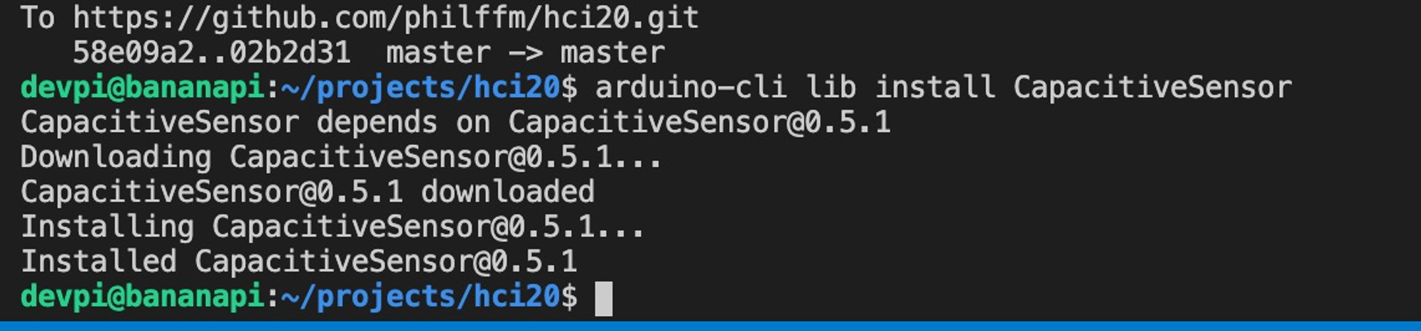
By the way I have to mention this: Installing libraries with the arduino-cli (command line interface) is so satisfying

Whatever I was trying, it was not possible for me to retrieve a value. I tried another power supply, different pins and asked my peer review partner to share his wiring.
Valid code, but not working (Arduino)
#include <CapacitiveSensor.h>
CapacitiveSensor touchSwitch = CapacitiveSensor(4, 2);

int LEDpin = 11;
void setup(){
    pinMode(LEDpin, OUTPUT);
    Serial.begin(9600);
}

void loop()
    {
    long start = millis();
    long val = touchSwitch.capacitiveSensor(30);

    if (val > 100) {
    digitalWrite(LEDpin, HIGH);
    } else {
    digitalWrite(LEDpin, LOW);
    }
    // print sensor output 1
    Serial.println(val);
}
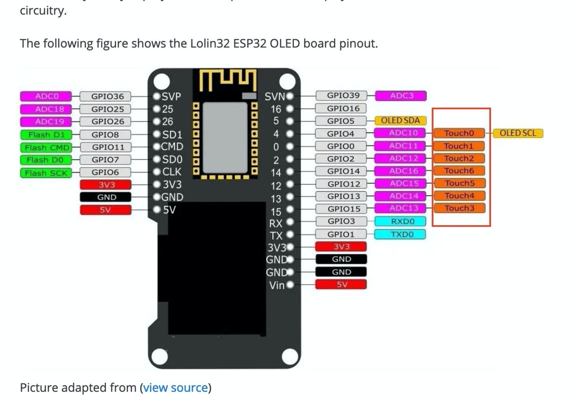
After a certain amount of time I realised that the project, I had in mind I wanted to create based on ESP32 hardware anyway (due to some perks such as WiFi and BLE and thus decided to do some research on how to implement a capacitive sensor there.
Eventually I found out that the ESP32 chip in general has pins for 10 touch points (my particular board model has 6. as some are reserved by the OLED screen)

Valid code, working (ESP32S)
void loop() {
  Serial.println(touchRead(T2));  // get value of Touch 2 pin = GPIO 2 / T2
  delay(1000);
  ArduinoOTA.handle();
  //runLED();

}
AWS3 Bonus (Or tinkering? Whatever)
Come on, dispense my pills finally.
Further thoughts
The Emotional Matrix
I was playing around before with displaying different text across the 8x32 Matrix module so never tried to adress just one piece of the panel. To my surprise, all of the modules were adressed, however with a bit of latency between them.


From Input to output

"If you understand an example, use it. If you don't understand an example, don't use it."
Switching devices
As I was lacking a few cables in comparison to the official HHS Arduino kit, I made an unusual decision.
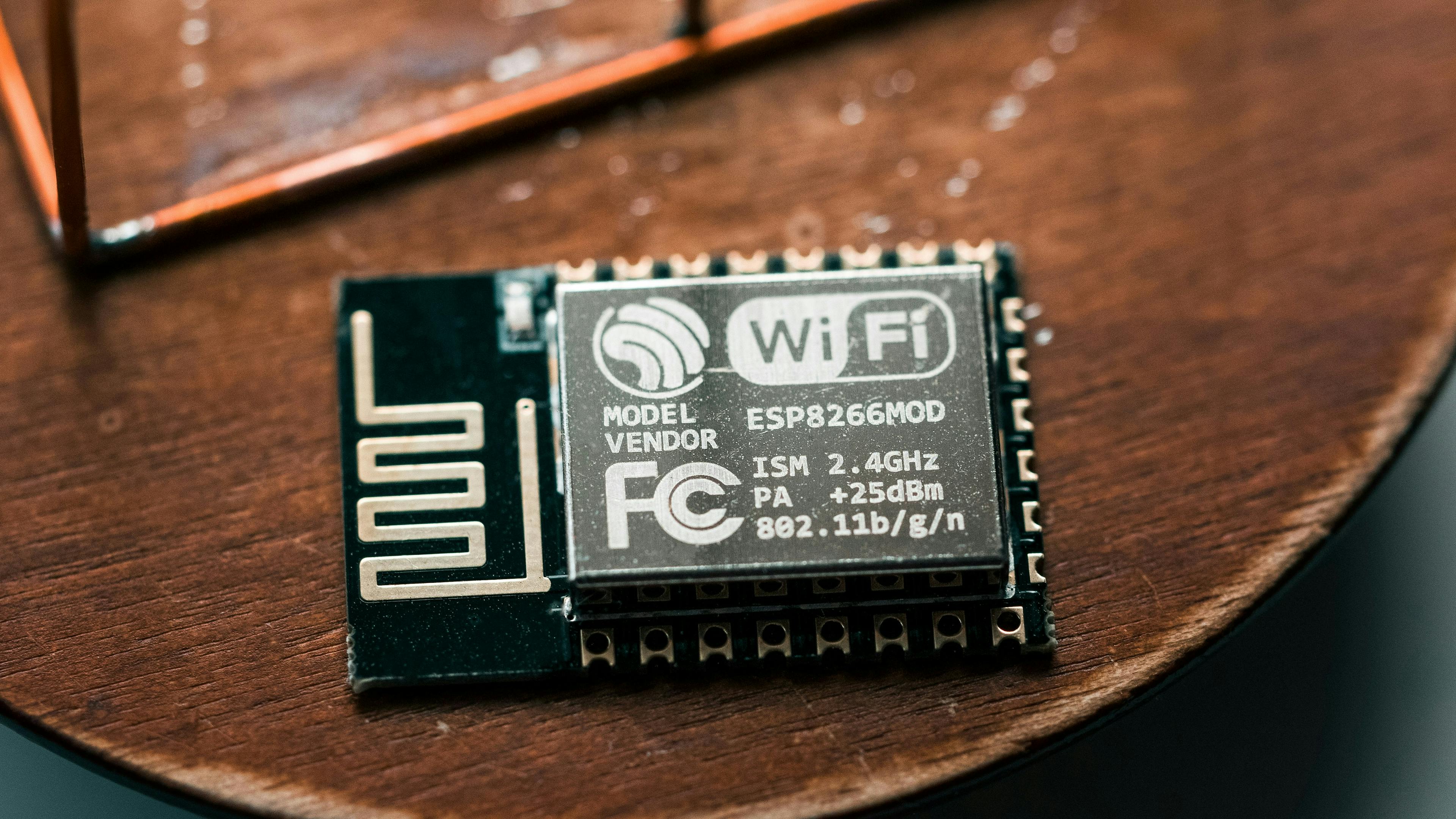
More cables would have been 5 Euros - but hey , why would I pay 5 Euros if I could also get the Cables + ESP8266 (Whatever it might be, it says WiFi - maybe a WiFi chip?) + OLED Display + a small bread board + a BMP280 (better temperature / humidity sensor than the basic ones + a fancy USB cable) for 17 Euros?
After talking to a friend in the mean time, I realised this was not just a WiFi chip but basically a fully mature, programmable microcomputer, just as the Arduino - but way smaller and thus even better suited for... What are we doing here? True, wearable prototyping! It is running on 3.3V though, so fine for most of the stuff but something to keep in mind.
So I carried on with the Arduino IDE but soon realised the integration was not as smooth as I expected.
The NodeMCU with ESP8266 chip requires some additional libraries and works with different pin names
And well, this was the only thing I needed to carry on with basically the same Arduino code. The only thing to take into account basically was the PIN-mapping.


